RC5 Decoder with PIC Microcontroller
Description
This project shows how to decode IR remote controls which use RC5 code with a PIC microcontroller.
With being able to read IR remote control command it is possible to use standard remote controls as input device for a microcontroller.
RC5 Basics
Introduction
The RC5 protocol was developed by Philips as consumer IR (infrared) remote control communication protocol for consumer electronics.
Data Format
The RC5 code is 14 bits long. Each code includes 2 start bits, 1 toggle bit, a 5 bit address (or system) and a 6 bit command. This allows for 32 systems (like TV, CD, video, etc.) and 64 commands per system.
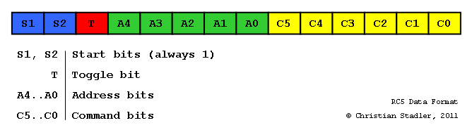
The two start bit indicate the start of the RC5 frame.
Note:
After some time 64 commands per system didn't seem to be enough though, so an extra command bit
was added to allow 128 commands. To maintain backward compatibility with the standard RC5, the format
itself was left unchanged. The second start bit (S2) was replaced by C6. The resulting format is called Extended RC5.
The toggle bit T changes each time a new command is transmitted. It allows detection if the same key is pressed twice. Since a code is being sent as long as the key is pressed, a short release of the button and again pressing it again would otherwise not be recognized.
The address bits A5..A0 specifies the system (or device) the command shall be sent to, e.g. TV, CD, Video, etc.
Finally, the command bits specify the command to be performed.
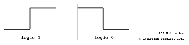
Modulation
RC5 uses Manchester coding. Manchester coding has a transition in the middle of a bit.
A logical 1 is coded as a 0 in the first half of the bit and a 1 in the second half of the bit.
A logical 0 is coded as a 1 in the first half of the bit and a 0 in the second half of the bit.
Important hint:
Most of the IR-Receivers (e.g. the SFH5110 or TSOP1736) have an inverted output!
So a logical 1 at the output of the IR-Receiver will be represented by a 1 in
the first half of the bit and a 0 in the second half, a logical 0 will be
represented by 0 in the first half of the bit and a 1 in the second half.
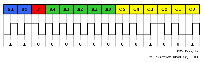
RC5 Example
In the example below an example of an RC5 code which shows how the information is coded. In this example the toggle bit is 0, the address is also 0 and the command is 9, i.e. key '9' has been pressed.
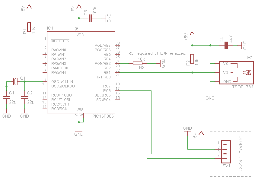
Hardware
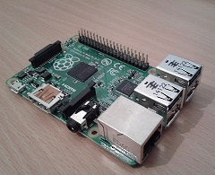
As IR-Receiver I used a SFH5110-36 which is a IR-Receiver for Remote Control Systems. Also other IR-Receivers like, a SFH506-36 or TSOP1736 will work. Important is that the IR-Receiver is designed for a carrier frequency of 36kHz (which is the carrier frequency used by RC5).
The interface to the PIC microcontroller is very simple, the output of the IR-Receiver just needs to be connected to an "interrupt on-change" pin. I used a PIC16F886 where port B has "interrupt on-change" capability, so I connected it to port pin RB1. Further I also added a pull-up resistor (according to the datasheet this is optional).
Software
The RC5 software driver is written in C language and currently is compatible to CCS C compiler and Microchip C18 compiler.
Decoding
The decoding happens in the interrupt service routine of the "on-change" interrupt of port B, i.e. every time the logic level on the pin changes the decoding is done. As time base for the decoding a free running hardware timer of the microcontroller is used, so the timer can also be used for other things. In my demo application, I used timer 0 of the PIC which is configured to increment every 25.6us. The resolution of 25.6us provides enough accuracy for decoding the RC5 signal (a half bit is 889us long). Timer 0 is a 8 bit timer, with a timer increment every 25.6us an overflow will occur every 25.6us * 256 = 6553us. Since the bit length is 1778us which is (much) smaller than the timer overflow time this configuration is ok for decoding the RC5 signal.
RC5 Driver Configuration
To use the RC5 driver in your projects, the following things need to be configured.
First of all, the pin where the IR-Receiver is connect needs to be specified via the #define RC5_DATA_PIN. In the demo I used RB1. I.e. PIN_B1 needs to be replaced by the pin where the IR-Receiver is connected to. Important is that the pin which shall be used has "on-change" interrupt capability!
#define RC5_DATA_PIN PIN_B1 /* IR sensor (SFH5110-36) connected to RB1 */
Since a hardware timer is required as time base for decoding the RC5 signal, the driver needs to know how often the timer is incremented per millisecond. In my example timer 0 is used which is configured to increment every 25.6us, hence it will increment 1000us/25.6us = 39 times per 1ms (1000us).
#define RC5_TICKS_PER_MS      (1000/26)     /* timer increments every 25.6us, */
/* i.e. around 39 ticks per millisecond */
The driver also needs to know which timer is used or to be more precise how to get the current timer value. To achieve this, the macro RC5_GetTimer() needs to be defined. This macro shall return the current timer value. In the demo I used timer 0, hence it is configured to "get_timer0()" which is a CCS built in function which returns the timer 0 register value.
#define RC5_GetTimer() get_timer0() /* timer0 shall be used for RC5 decoding */
Since the RC5 driver is no properly configured, we have to include the RC5 driver itself.
#include "rc5.h" /* RC5 driver include */
Now we need to add the interrupt handler which calls the RC5 decoding function of the RC5 driver. The decoding function is RC5_InterruptHandler().
/*****************************************************************************/
/* Interrupt_RB                                                              */
/*                                                                           */
/* Port B change interrupt service routine.                                  */
/* Used to decode RC5 IR signal.                                             */
/*****************************************************************************/
#INT_RB
void Interrupt_RB(void)
{
RC5_InterruptHandler();
clear_interrupt(INT_RB);
}
And finally, we need to configure the timer 0 which will be the time base for the RC5 decoding function and enable the "on-change" interrupt.
/* FOSC/4 is timer source */
/* FOSC = 20MHz => 5MHz, i.e. timer increment every t = 1/(FOSC/4) = 200ns */
/* with prescaler of 128 timer will increment every 25.6us */
setup_timer_0(RTCC_INTERNAL|RTCC_DIV_128);
/* configure port B interrupt on change */
set_tris_b(0xFF);               /* all pins on port B are input */
input_b();                      /* read port B to clear mismatch condition */
clear_interrupt(INT_RB);        /* clear port B interrupt flag */
enable_interrupts(INT_RB1);     /* enable RB1 interrupt on change */
/* global interrupt enable */
enable_interrupts(GLOBAL);
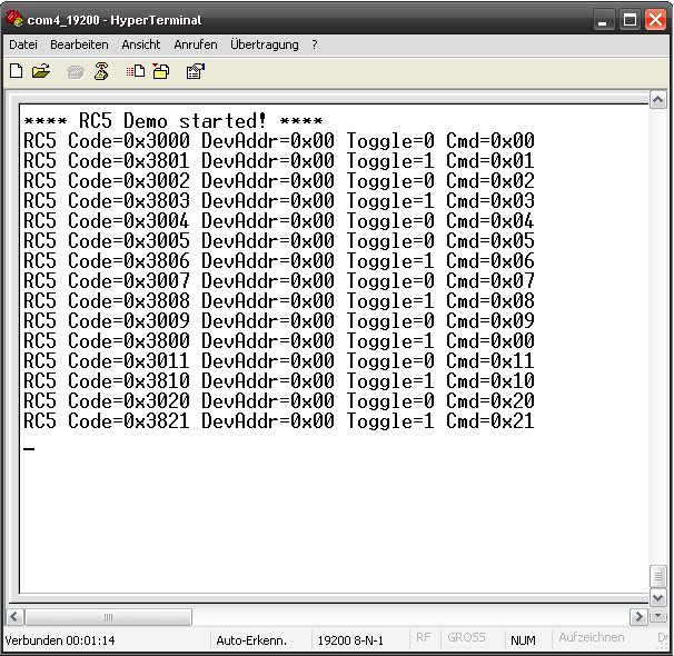
RC5 Decoder Demo Application
Here a full demo application showing the RC5 driver usage. A full CCS C project and Microchip C18 project can be downloaded in the Download section below.
The following explainations are done based on the CCS C project, but are very simialr for the C18 compiler.
/*** FILEHEADER **************************************************************** * * FILENAME: rc5demo.c * DATE: 26.07.2011 * AUTHOR: Christian Stadler * * DESCRIPTION: RC5 demo which shows usage of RC decoder driver. * ******************************************************************************/ /* make compiler case sensitive */ #pragma case #include#include "types.h" /* --- RC5 driver configuration --- */ #define RC5_DATA_PIN PIN_B1 /* IR sensor (SFH5110-36) connected to RB1 */ #define RC5_TICKS_PER_MS (1000/26) /* timer increments every 25.6us, */ /* i.e. around 39 ticks per millisecond */ #define RC5_GetTimer() get_timer0() /* timer0 shall be used for RC5 decoding */ #include "rc5.h" /* RC5 driver include */ /* --- macros to switch on/off LED --- */ #define Led_On() output_high(PIN_A0) #define Led_Off() output_low(PIN_A0) /*****************************************************************************/ /* Interrupt_RB */ /* */ /* Port B change interrupt service routine. */ /* Used to decode RC5 IR signal. */ /*****************************************************************************/ #INT_RB void Interrupt_RB(void) { Led_On(); RC5_InterruptHandler(); clear_interrupt(INT_RB); Led_Off(); } /*****************************************************************************/ /* main */ /* */ /* Configures timer0 as time base for RC5 decoding and enables port B */ /* interrupt on change. */ /* Main loop checks if a RC5 code has been received and writes the code */ /* to the RS232 interface. */ /*****************************************************************************/ /* NOTE: Currently it only works if PIC is reset after programming? */ void main() { uint16 rc5code; /* FOSC/4 is timer source */ /* FOSC = 20MHz => 5MHz, i.e. timer increment every t = 1/(FOSC/4) = 200ns */ /* with prescaler of 128 timer will increment every 25.6us */ setup_timer_0(RTCC_INTERNAL|RTCC_DIV_128); /* configure port B interrupt on change */ set_tris_b(0xFF); /* all pins on port B are input */ input_b(); /* read port B to clear mismatch condition */ clear_interrupt(INT_RB); /* clear port B interrupt flag */ enable_interrupts(INT_RB1); /* enable RB1 interrupt on change */ /* global interrupt enable */ enable_interrupts(GLOBAL); printf("**** RC5 Demo started! **** \n\r"); while(TRUE) { /* check if new data is available */ if (RC5_CodeReady()) { /* get code */ rc5code = RC5_GetCode(); printf("RC5 Code=0x%04LX DevAddr=0x%02X Toggle=%d Cmd=0x%02X\n\r", rc5code, RC5_GetDeviceAddr(rc5code), RC5_GetToggleBit(rc5code), RC5_GetCmd(rc5code)); } /* this function increments the RC5 timeout timer */ /* NOTE: Decoding will also work without calling this function, but */ /* it could happen that RC5 codes are sometimes not getting */ /* recognized because of decoding state machine stucks due */ /* to erroneous RC5 signal. */ RC5_TimeoutIncrement(); } }
Download
- Demo project (CCS C Compiler): rc5_decoder_ccs_111016.zip
- Demo project (Microchip C18 Compiler): rc5_decoder_c18_111019.zip
- Driver source code (CCS C Compiler, Microchip C18 Compiler): rc5.h
Links
Here some usefull links:
- http://en.wikipedia.org/wiki/RC-5: Basic information regarding RC5 code/protocol
- http://www.nenya.be/beor/electronics/rc5.htm: Another source of RC5 protocol description
- http://www.sprut.de/electronic/ir/rc5.htm: RC5 Code description (German)
- http://www.ccsinfo.com/forum/viewtopic.php?p=152585#152585: Troubleshooting RC5 driver integration into PIC project